From a STEP file to MJCF: a small arm, run in MuJoCo
To get an MJCF from a STEP file, bring the assembly into ProtoJoint, add the joints, which a STEP file does not carry, give the parts their materials, and export the robot with MJCF ticked: the zip holds small_arm.xml, the robot, and scene.xml, which adds a floor and lights, and MuJoCo opens it. This post does it for a three-part arm, from the STEP file to MuJoCo, and measures what came out: the masses are the volumes times the densities, the pivot holes lie on the joint’s axis, and a positive shoulder_lift lifts the arm. The STEP file and the export are below to download.
What is in the STEP file?
A small desk arm of three parts: a base, a disc 140 mm across and 20 mm thick; a block 50 × 50 × 100 mm standing on it, with a 12 mm pivot hole through it, 100 mm above the floor; and an upper arm, a bar 180 × 30 × 20 mm beside the block with two 12 mm holes 140 mm apart, the first on the pivot. It was written by the editor from the small arm’s replay, which builds the arm and exports it: the file a CAD program writes when you save an assembly as STEP. The replay ends with the arm posed, turned 35° and lifted 50°, so I set both joints back to zero before saving: the parts in the file stand as they were modelled.
The file, small_arm.step, is 51,084 bytes. It names the design desk_arm and holds three parts placed in it, and, as I searched it for a joint or a kinematic entity, it holds none of either: a STEP file says what the parts are and where they stand, not how they move. That is why the joints are the part you add.
How does it come in?
A fresh editor, Assemble › More › Import, the file chosen: three parts come in, the shoulder, the upper arm and the base, which the file calls Body1 (bringing in an assembly has the rest). Their volumes, as the editor measures them, are the replay’s to the tenth of a cubic millimetre: 307,876.1 mm³ for the base, 244,345.1 for the shoulder and 103,476.1 for the arm. So the volumes came through STEP unchanged.
What do I add?
Two revolute joints, where the arm turns, and a material for each part.
| Joint | Moves | On | About | Limits |
|---|---|---|---|---|
shoulder_pan | the shoulder | the base | the vertical through the base’s centre | −150° to 150° |
shoulder_lift | the upper arm | the shoulder | the pivot hole’s axis, at (0, −45, 100) mm | −30° to 120° |
Both are as-built joints, so the parts stay where they stand and that pose is the joints’ zero. By hand it is Shift+J, the as-built joint, as the replay shows: set Type to Revolute (it starts as Rigid), click the part that moves, then the part it turns on, then a round edge on the axis, the rim of the base for the pan and the edge of the pivot hole for the lift; type the limits, and name the joint once it is made. Here I made them with add_joint, the action Eleph and an AI app over MCP call, with the axes and limits of the table. The pan joint I put 10 mm up the base’s axis; the replay picks the rim of the base’s top, 20 mm up the same axis. The materials: aluminium 6061 for the base and the arm, PLA for the shoulder.
The robot panel (Robot › Export robot) had no errors. Until the base is pinned to the world it warns No part is pinned: small_arm is the root for now
; pin the base (right-click it, Pin) and the warning goes, with the same root. The root link is small_arm, the component the import made for the file, which holds the base, and the MJCF has no free joint on it, so the arm stands fixed to the world.
What does the export hold?
One zip, small_arm.zip, of 17 files: the URDF (small_arm.urdf, and the ROS 2 package’s copy), small_arm.xml and scene.xml for MuJoCo, a ROS 2 package with its launch files, a Gazebo world, and meshes/, one STL for each link. The URDF has the three links and the two revolute joints. The MJCF’s bodies and actuators:
<worldbody>
  <body name="small_arm" pos="0 0 0" quat="1 0 0 0">
    <inertial pos="0 0 0.01" mass="0.83126541614" fullinertia="0.00104600898198 0.00104600898198 0.00203660026954 0 0 0"/>
    <geom type="mesh" mesh="small_arm" material="color_6f9fe0" contype="1" conaffinity="0"/>
    <body name="shoulder" pos="0 0 0.01" quat="0.707106781187 0 0 -0.707106781187">
      <joint name="shoulder_pan" type="hinge" axis="0 0 1" range="-2.61799387799 2.61799387799" damping="0.772665191801"/>
      <inertial pos="0 0 0.0593057115521" mass="0.302987965197" fullinertia="0.000316333567475 0.000314935835204 0.00012764271777 0 0 0"/>
      <geom type="mesh" mesh="shoulder" material="color_ff8c1a" contype="1" conaffinity="0"/>
      <body name="upper_arm" pos="0.045 0 0.09" quat="0.707106781187 0 0.707106781187 0">
        <joint name="shoulder_lift" type="hinge" axis="0 0 1" range="-0.523598775598 2.09439510239" damping="0.635432375657"/>
        <inertial pos="0 0.07 -0.01" mass="0.279385487763" fullinertia="0.00073667180902 0.000031072918982 0.000749119028818 0 0 0"/>
        <geom type="mesh" mesh="upper_arm" material="color_eef2f6" contype="1" conaffinity="0"/>
      </body>
    </body>
  </body>
</worldbody>
<actuator>
  <position name="shoulder_pan" joint="shoulder_pan" kp="57.9498893851" ctrlrange="-2.61799387799 2.61799387799" forcerange="-10 10"/>
  <position name="shoulder_lift" joint="shoulder_lift" kp="47.6574281742" ctrlrange="-0.523598775598 2.09439510239" forcerange="-10 10"/>
</actuator>
A body’s frame is its joint’s frame and the meshes are in it, in metres, radians and kilograms. A link’s inertial block is its mass, its centre of mass and its inertia tensor about it, from the exact solid and its material. A link collides with the floor but not with the other links (contype="1" conaffinity="0"), and each joint has a position actuator limited to the joint’s range.
Run it in MuJoCo
MuJoCo needs only Python: pip install mujoco, then, in the folder where you unpacked the zip:
python -m mujoco.viewer --mjcf=small_arm/scene.xml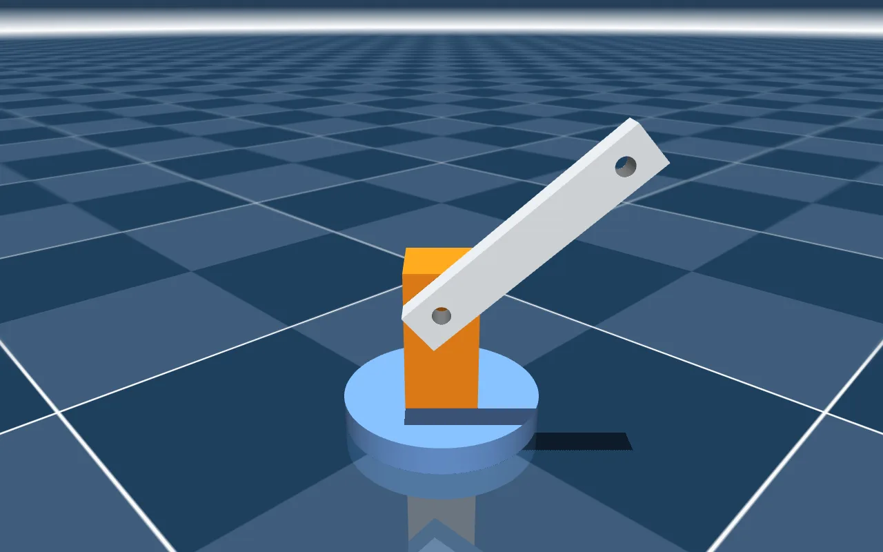
The numbers in this post come from a few lines of Python on the same files:
import mujoco
import numpy as np

m = mujoco.MjModel.from_xml_path("small_arm/scene.xml")
d = mujoco.MjData(m)
print(m.nbody, m.njnt, m.nu, round(m.body_mass.sum(), 6))

lift, arm = m.joint("shoulder_lift"), m.body("upper_arm")
for deg in (-30, 0, 60, 120):
    d.qpos[lift.qposadr[0]] = np.radians(deg)
    mujoco.mj_forward(m, d)
    print(deg, np.round(d.xipos[arm.id] * 1000, 1))

mujoco.mj_resetData(m, d)
for _ in range(1000):          # 2 s at the model's 0.002 s step
    mujoco.mj_step(m, d)
print(np.degrees(d.qpos).round(3))
which prints, on MuJoCo 3.17.0 and on 4.0.0 alike:
4 2 2 1.413639
-30 [ 60.6 -35.   65. ]
0 [ 70. -35. 100.]
60 [ 35.  -35.  160.6]
120 [-35.  -35.  160.6]
[ 0.    -0.231]
What the numbers say
- The model: 4 bodies, the world and the three links, 2 joints and 2 actuators, and a total mass of 1.413639 kg.
- The masses are the solids’: the base weighs 0.831265 kg, which is its 307,876.1 mm³ in aluminium 6061 at 2700 kg/m³; the shoulder 0.302988 kg, 244,345.1 mm³ of PLA at 1240 kg/m³; the arm 0.279385 kg, 103,476.1 mm³ of aluminium. Before rounding, the three add to the 1.413639 above.
- The joints are on the holes: at zero, in MuJoCo’s world, the shoulder’s frame is at (0, 0, 0.01) m, 10 mm up on the base’s axis, and the upper arm’s at (0, −0.045, 0.1) m, with the joint’s axis along −y. Measured on the exported meshes, 184 of the shoulder’s 232 vertices and 121 of the arm’s 306 lie 6.000 mm from that axis, the wall of a 12 mm hole, and the arm’s stay 6.0000 mm from it with the joint at 60° and at 120°: the arm turns on the pin, not beside it.
- Which way it turns: a positive
shoulder_liftlifts the arm. At zero the bar lies level, its centre of mass 70.0 mm out from the pivot and 100.0 mm up, half the 140 mm between its holes; at 60° it is 160.6 mm up and 35.0 mm out; at 120° it has gone over the top, 160.6 mm up and 35.0 mm behind; at −30° it is 65.0 mm up. Turned 90°,shoulder_pancarries the arm’s centre of mass from (70.0, −35.0) mm to (35.0, 70.0): counter-clockwise seen from above. - The ranges: −150° to 150° and −30° to 120°, as set. Each actuator, sent to either end of its range for 2 s, brings its joint to within 0.1° of it.
- Left at zero: with every actuator at zero and gravity on, the arm sits at the end of 2 s with the lift 0.231° below zero. That is the arm’s weight on its actuator: 0.279385 kg with its centre of mass 0.070 m out pulls with 0.279385 × 9.81 × 0.070 = 0.1919 N·m, and the actuator’s gain is 47.657 N·m per radian, so it gives way 0.1919 / 47.657 = 0.00403 rad, which is 0.231°. There are no contacts at the zero pose.
- Driven: both actuators through a slow sine for 4 s, nothing goes NaN.
Download the files
- small_arm.step, 51 KB: the STEP file the post starts from, to import into the editor with Assemble › More › Import.
- small_arm.zip, 32 KB: the export as it came out, 17 files, and the licence added as
small_arm/LICENSE; itspackage.xmlstill has the export’s placeholders for the maintainer and the licence.
Both files are under the MIT licence, copyright ProtoJoint AI: use them, change them and share them, commercially too, as long as the copyright line and the licence go with them.
Questions
Why do I add the joints myself?
A STEP file holds the shapes and where they stand; as I looked for one in this file, it has no joint in it. Where a part turns or slides is something only you know, and the import leaves the assembly as it is. A joint takes a click on the circle of a hole or a shaft on each of the two parts, and a limit.
Does it work from a file from another CAD program?
This post ran one file, the one above, which ProtoJoint itself wrote. A STEP assembly from another CAD program comes in as a component for every subassembly and part, and bringing in an assembly says what comes across; the joints and the materials are added the same way.
What about mass: do I have to set it?
Give each part a material and the mass and inertia come from its solid, as above. A bought part you know only by its weight, such as a motor, keeps its shape’s inertia scaled to the mass you give it; a part printed at an infill can be weighed as printed, as the CAD to URDF guide says.
Does the arm do anything on its own?
No. It holds each joint where its actuator is told, and falls into the pose gravity allows where it is not. A controller of your own, in MuJoCo’s Python or elsewhere, commands the two actuators; their ranges are the joints’.
Can I get the URDF from the same file?
Yes: the same export holds it, with the three links and the two joints, and so do the ROS 2 package and the Gazebo files. CAD to URDF goes through that side.
12-servo robot dog: CAD to MuJoCo and Gazebo
Build a twelve-servo robot dog in the browser, draw one leg round its servos, mirror and copy it, joint it at hip and knee, and export a floating base to MuJoCo, Gazebo and ROS 2, with the files to download.
CAD to URDF: export from a model or STEP file
Turn a CAD model or a STEP assembly into a URDF in your browser: links from parts, joints from the assembly, inertia from the exact solids, and MJCF for MuJoCo. What goes in, what comes out, and a six-servo arm exported.
Pick-and-place gantry: T-slot to Gazebo, MuJoCo
Build a three-axis pick-and-place gantry in the browser on a T-slot frame, with MGN12 rails, NEMA 17 belts and a Pi camera, join it with three sliders and export URDF, SDF, MJCF and a ROS 2 package.
CAD to URDF: eight mistakes to avoid
Why a robot from CAD loses links, refuses to load or moves wrong in Gazebo and MuJoCo: inertia, default masses, massless links, frames, axes, closed loops, slider limits and heavy meshes, with each check.