Sketches that stay put
Snaps become constraints, typed numbers become dimensions. The sketch shows what is still free, and turns down a constraint that would fight the others.
Parametric CAD · in your browser · with AI
Describe a part in one sentence and Eleph, the built-in AI design assistant, models it, in sketches, features and named dimensions you can check and edit. Under it is a full parametric CAD in a browser tab: constrained sketches, assemblies with joints, STEP, STL and DXF, on Linux, a Chromebook, a Mac or Windows.

A NEMA 17 motor mount that bolts to a 2020 aluminium extrusion, with slotted holes to tension the belt.
I've built the NEMA 17 mount: an L-bracket, 60 × 25 × 67 mm, that bolts into the extrusion's T-slots on two faces. One parameter, travel, sets all five slots for ±3 mm of belt travel. No clashes between the 12 bodies.
AThe CAD under it
Eleph works the way you do, in sketches, features and named dimensions, and this is what they add up to: an 11 : 1 cycloidal reducer modelled in ProtoJoint one feature at a time, 87 solids down to the last bearing ball. Cut it open across the disc or along the shaft, drag it round, and watch two discs roll on twelve ring pins while the output turns once for every eleven turns in.
See it modelled, step by step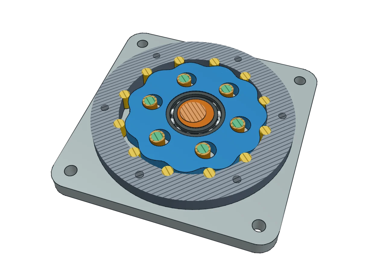
BWhat comes in the tab
Not a toy and not a viewer: sketches, features, parameters, assemblies and the files that leave with you.
Snaps become constraints, typed numbers become dimensions. The sketch shows what is still free, and turns down a constraint that would fight the others.
Extrude, revolve, sweep, loft, shell, draft, pattern, thread, coil. Roll back to any step, change it, and everything after it follows.
Type Width + 2*Wall into any field. Change one parameter and the whole model resizes around it.
Three rounded edges meeting at one corner, a pocket rounded at its rim and its floor in one go, a radius that changes along an edge: each comes out as one watertight solid, ready to print or machine.
Rigid, revolute, slider, cylindrical, pin-slot, planar and ball joints, motion links, limits, interference checks, mass from the exact solids.
Yes, those. Parts and assemblies saved since 2015, each with its material, opened without the program that made them. STEP and Parasolid too.
STEP for other CAD, 3MF, STL or OBJ for the printer at the refinement you choose, DXF and SVG for the laser and the router.
Lay out an aluminium extrusion frame, get every cut length with its mass and price, and check stress, deflection and buckling on a beam model.
CTwo jobs, all the way to the file
ROS 2 and LeRobot builders
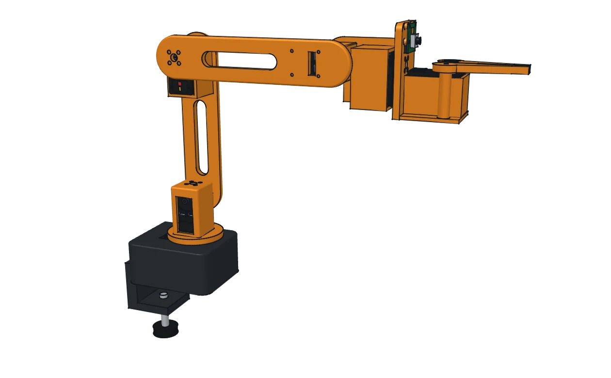
Parts become links, joints become joints, and every link’s inertia comes from its exact solid and material. Drag the joints to check it, then export URDF, MJCF or SDF, or a whole ROS 2 package with a launch file.
Robot exportLaser cutters and CNC routers
Material thickness is a parameter: change 3 mm to 6 mm and every finger joint follows. Living hinges, kerf added at export, and SVG or DXF in the colour layers your laser software reads.
Laser and CNCDWhere it runs
Any current Chrome or Edge will do, on whatever the computer runs. The first visit loads about 13 MB; after that the browser keeps it and ProtoJoint opens at once.
EYour move
Sketch it, extrude it, export it. If anything gets in the way, tell us and it goes on the drawing board.