A pick-and-place gantry from T-slot to Gazebo and MuJoCo
A Cartesian gantry can go from a frame of T-slot extrusions to a robot that moves in Gazebo and MuJoCo without writing any XML: build the frame with the Frame tool, put rails and carriages from the parts library on it, make each moving assembly a part of its own, join them with slider joints along the rails, and export. This one is a pick-and-place on a 500 by 400 by 300 mm frame, on MGN12 rails, with NEMA 17 steppers on GT2 belts and a Raspberry Pi Camera Module 3 over a tray of blocks, and its export is a ROS 2 package with URDF, SDF and MJCF. Below are how it was modelled, the export settings, the commands for each simulator, what we checked, and the files to download.
What is the gantry?
A frame 500 by 400 by 300 mm outside, 2020 extrusions for the legs and the bottom rails and 2040 on top, with a 6 mm tray on the bottom rails and four 25 mm blocks on it to pick. Three axes move a tool head over the tray, each on MGN12 linear rails with MGN12H carriages:
| Joint | What moves | On | Travel | Positive is |
|---|---|---|---|---|
axis_y | the gantry, front to back | two 400 mm rails on the top rails | −110 to 120 mm | toward the back, +Y |
axis_x | the carriage, side to side | a 460 mm rail on the front of the gantry’s 2040 beam | −180 to 180 mm | to the right seen from the front, +X |
axis_z | the tool head, up and down | a 220 mm rail on a 2020 bar that slides through the Z carriage | −90 to 40 mm | up, +Z |
The X and Y axes each have a NEMA 17 stepper, 40 mm long, with a 20-tooth GT2 pulley, an idler at the other end and a 6 mm belt between them; the Z bar is modelled without a drive. The tool head carries a vacuum cup and a Raspberry Pi Camera Module 3 looking straight down at the tray.
Watch it being built
The whole gantry was made one tool at a time, and how is recorded as a replay. Open the gantry’s replay and the editor builds it in front of you, each sketch, extrusion, part, joint and setting as a person makes it, then exports it.
How was it modelled?
- The frame comes from the Frame tool, sized from the outside, and the beam across the gantry is a member of the Frame tool too.
- The rails are the parts library’s MGN12, cut to length when inserted, and the carriages its MGN12H. The library’s NEMA 17 is a 17HS4401, 280 g, and its 20-tooth GT2 pulley has a 12.73 mm pitch circle.
- Four parts. What stays still is
base_link, pinned: the frame, the tray and its blocks, the Y rails, the Y stepper and its belt. The gantry is a part with its feet on the Y carriages, its 2040 beam, the X rail, the X stepper and its belt; the carriage is a part with the X carriage, its plate and the Z carriage; the tool head is a part with the Z bar, its rail, the cup and the camera. The parts library’s pieces sit inside the part they move with, so each belongs to that part’s link. - Three slider joints, one along each rail, made where the parts were modelled (As-built joint): that place is each axis’s zero, and the travel in the table is measured from it.
- Materials, one for each part:
base_link, the gantry and the carriage are 6061 aluminium, 2700 kg/m³, and the tool head is PLA, 1240 kg/m³. Colour is not material here: the tray is coloured like birch plywood and the Y drive’s two end plates orange like printed PLA, but they weigh as the aluminium ofbase_link, and so do the two belts. The frame’s members, the tool head’s 2020 bar among them, weigh what their extrusions weigh per metre, whatever their part is made of.
The belts are there to look at. A slider joint moves each part along its rail; a belt is part of a link’s mesh and pulls nothing, the Y belt in base_link’s and the X belt in the gantry’s.
How was it exported?
Open Export in the header and choose Export Robot (URDF / MJCF / SDF)…. The three sliders become prismatic joints, and the panel finds the camera by itself. The base stays fixed: the gantry stands on a bench.
- Effort 63 N and Velocity 0.5 m/s, into every joint’s limits; on a prismatic joint they are a force and a speed. 63 N is what the belt pulls at the 17HS4401’s holding torque, 40 N·cm in MotionKing’s catalogue1, on the pulley’s 12.73 mm pitch circle: 0.40 N·m over 6.366 mm. It pulls less the faster the motor turns, by how much depending on the driver and the supply. 0.5 m/s turns the pulley at 750 rpm.
- Formats: URDF, the ROS 2 package, SDF and MJCF.
The export weighs the gantry at 9.15 kg: base_link 6.93 kg, the gantry 1.55 kg, the carriage 302 g and the tool head 365 g; the camera’s two frames weigh nothing. The parts library’s pieces weigh what their makers give, 280 g a stepper, 54 g a carriage, 7 g a pulley and 0.65 g for each millimetre of rail, and the Frame tool’s members weigh their extrusions’ catalogue weight per metre. The rest is its volume times its part’s material: in base_link that is 3.2 kg, of which the tray, 480 by 380 by 6 mm of 6061 aluminium, is about 2.95 kg. A library piece’s inertia is its shape’s scaled to its mass, as the export’s panel says; the rest are exact for their volume and density. To use the weight of your own tray, make the tray a part of its own, welded to base_link, and type its mass into Given mass: that field sets a whole part’s mass.
With the four formats ticked, Export zip saves one zip:
gantry/
  gantry.urdf  urdf/gantry.urdf           URDF: meshes beside it, or by package://
  package.xml  CMakeLists.txt  launch/  config/  rviz/  worlds/  scripts/
                                          the ROS 2 package
  gantry.xml  scene.xml                   MJCF, and a scene with a floor and lights
  model.sdf  model.config  world.sdf      SDF, for Gazebo without ROS
  meshes/                                 44 STL files, one per link and colour
  README.md                               the commands for each
It comes to about 0.77 MB. CAD to URDF says what each file holds.
See it in RViz
On Ubuntu 24.04 with ROS 2 Jazzy, unpack the zip into a workspace, build it and launch the display:
sudo apt install ros-dev-tools ros-jazzy-joint-state-publisher-gui   # colcon and the sliders, once
source /opt/ros/jazzy/setup.bash
mkdir -p ~/ros2_ws/src
python3 -m zipfile -e gantry.zip ~/ros2_ws/src/
cd ~/ros2_ws
colcon build --packages-select gantry
source install/setup.bash
ros2 launch gantry display.launch.py
RViz opens with the gantry, beside a window with a slider for each of the three axes. The commands assume ROS 2 Jazzy’s desktop install, ros-jazzy-desktop, which brings RViz; the sliders are a package of their own, ros-jazzy-joint-state-publisher-gui, installed in the first line. Before you share the package, put your name and a licence in its package.xml, which the export leaves as placeholders.
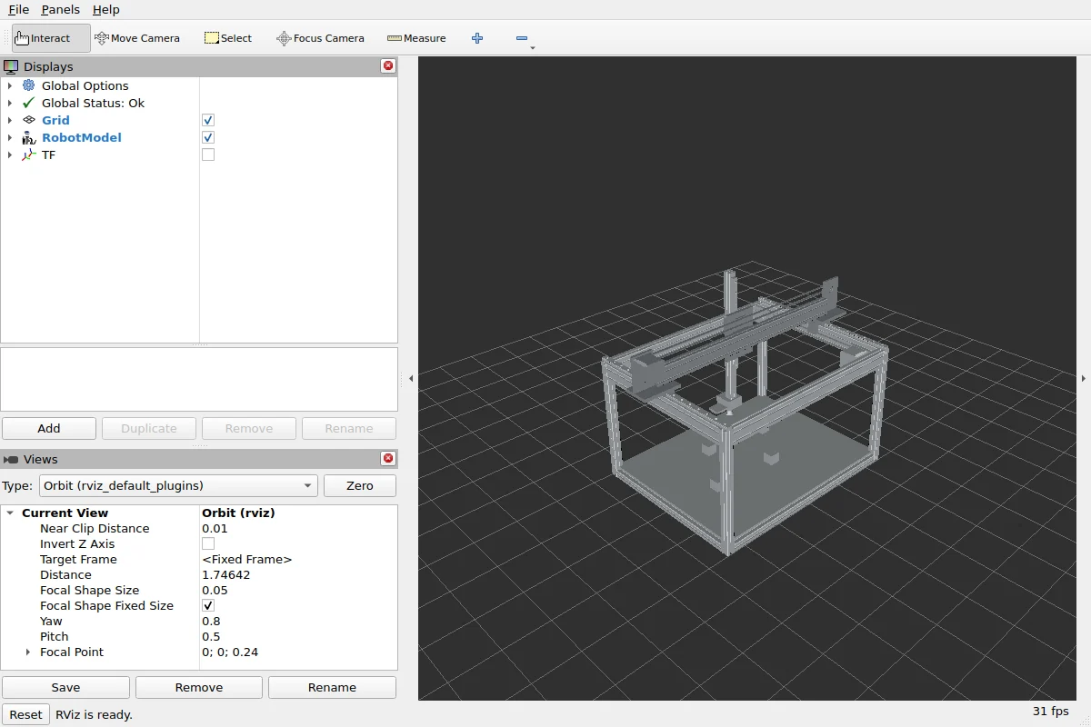
Run it in Gazebo
Gazebo Harmonic and its bridge to ROS 2 come with ros-jazzy-ros-gz. Close the display window first, so that two robots do not publish the same frames, and in a new terminal:
sudo apt install ros-jazzy-ros-gz     # once
source /opt/ros/jazzy/setup.bash
source ~/ros2_ws/install/setup.bash
ros2 launch gantry gazebo.launch.py
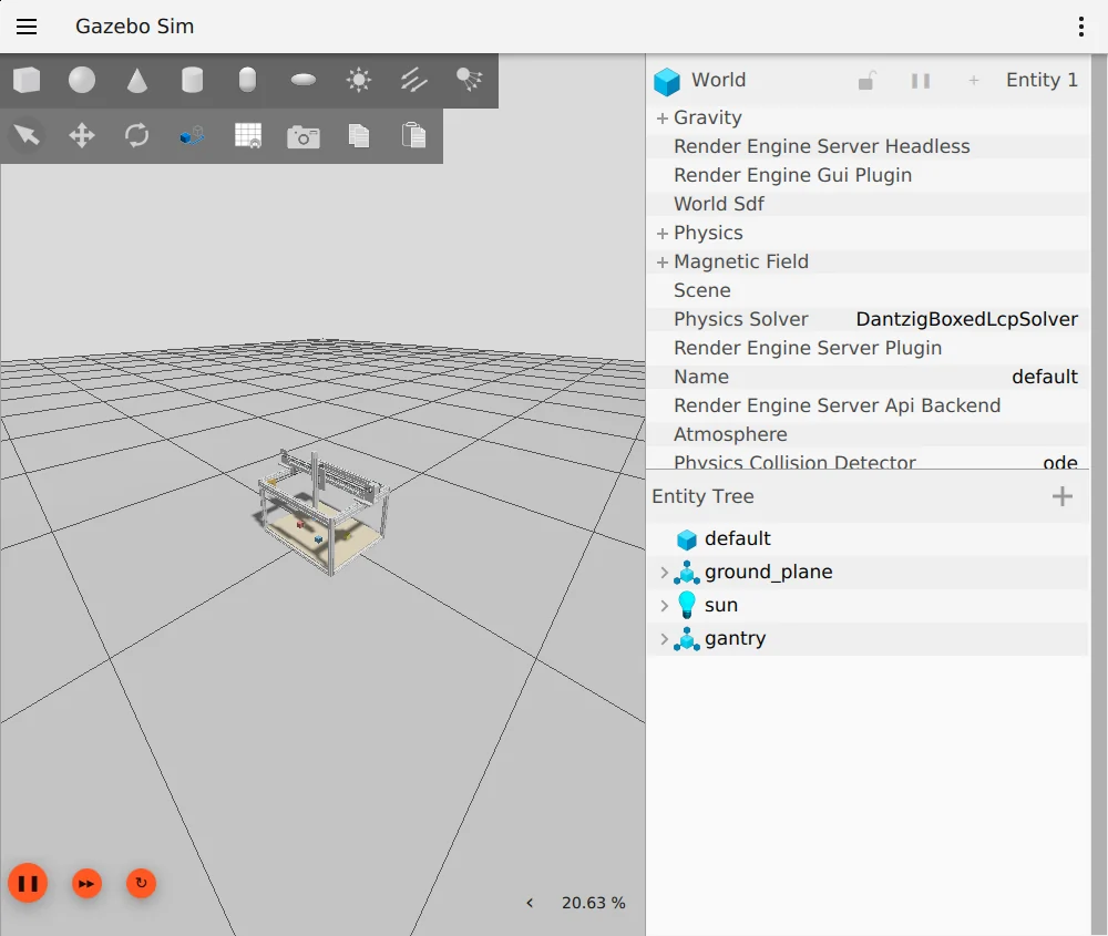
Gazebo opens with the gantry fixed where it stands in the design, and RViz beside it shows the robot, its frames and what the camera sees. Each axis is held by a position servo, at up to 0.45 m/s, nine tenths of the 0.5 m/s limit, and 63 N. To move one, publish a position in metres on its command topic, as the package’s README lists them. This one moves the carriage 100 mm to the right:
ros2 topic pub --once /axis_x/cmd_pos std_msgs/msg/Float64 "{data: 0.1}"With demo:=true added to the launch, the three axes swing together within their travel, each a little after the one before; it overrides your commands. The camera, 640 by 368 pixels with a 66° field of view at 50 Hz, publishes on /top_camera/image and /top_camera/camera_info.
Run it in MuJoCo
MuJoCo needs only Python. On Ubuntu 24.04 the system Python refuses pip install2, so install MuJoCo in a virtual environment, then, in the folder where you unpacked the zip:
sudo apt install python3-venv         # once
python3 -m venv ~/mujoco-venv
~/mujoco-venv/bin/pip install mujoco==3.17.0
~/mujoco-venv/bin/python -m mujoco.viewer --mjcf=gantry/scene.xml
3.17.0 is the version everything here was checked with. On Windows, pip install mujoco and python -m mujoco.viewer --mjcf=gantry/scene.xml are enough.
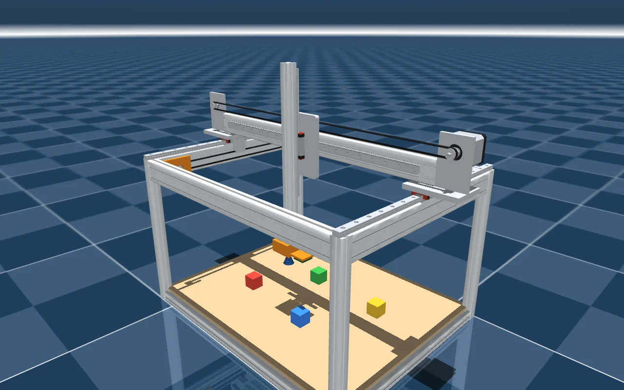
scene.xml puts the gantry, gantry.xml, on a floor with lights, its base fixed. Each axis has a position actuator, so the sliders under Control in the viewer’s right-hand panel move the gantry, the carriage and the tool head. The camera, top_camera, is a MuJoCo camera looking down at the tray: choose it under Camera in the Rendering section of the left-hand panel to see through it.
What was checked
The export below was made from the replay on 14 November 2026 and checked with the tools each format is for:
- ROS 2 Jazzy on Ubuntu 24.04:
check_urdfreads the URDF, 6 links in one tree, the four parts and the camera’s two frames; the package builds withcolcon; with robot_state_publisher running, every link is reachable through tf2; anddisplay.launch.pyopens RViz (above). - Gazebo Harmonic: its URDF reader keeps every link that moves, both free and welded to the world; the world loads and runs for 8 s, the camera’s
imageandcamera_infotopics give messages, andgazebo.launch.pyopens the gantry (above). - MuJoCo 3.17: the scene loads with the gantry’s 4 bodies, 3 slides, 3 actuators, each one’s range its joint’s travel, and the camera. Driven through a slow sine for 4 s, nothing goes NaN.
- Which way each axis moves, each moved alone in MuJoCo: as the table at the top says.
- That each axis follows its command, in MuJoCo and in Gazebo without ROS: each axis sent alone half the way to each end of its travel, the others held at zero:
axis_yto +60 and −55 mm,axis_xto ±90 mm,axis_zto +20 and −45 mm. In Gazebo each comes to rest at its command, within 5% of the way in 0.21 s at most. In MuJoCo so doaxis_yandaxis_x, in 0.31 s at most;axis_zrests 0.44 mm below its command, the tool head’s weight on its position actuator.
Download the files
- gantry.protojoint.json, 456 KB: the design, to open in the editor with Open, change and export again.
- gantry.zip, 766 KB: the export as it came out, the ROS 2 package with its URDF, SDF, MJCF and 44 meshes, as checked above, with the licence added as
gantry/LICENSE.
Both files are under the MIT licence, copyright ProtoJoint AI: use them, change them and share them, commercially too, as long as the copyright line and the licence go with them.
Questions
Why is each axis’s zero where it is?
An as-built joint takes the parts where they stand as its zero, so each axis’s zero is where its parts were modelled and every travel is counted from there. To have zero at an end of an axis instead, move the part to that end before making the joint.
Can it pick the blocks up?
Not in the export. The vacuum cup is a shape on the tool head, and the blocks are bodies of base_link, so in the simulators they are part of the fixed frame. Picking one takes the block as a body of its own and a grasp set up in the simulator, such as a weld you switch on and off.
Can I make it bigger?
Yes, with some work. Open the design file in the editor (Open), change the frame’s size and the rails’ lengths, then move or redraw the beam, the tray, the belts and the plates to match, and set each joint’s travel again before you export: the links, joints, masses and meshes are then written anew.
Sources
- DatasheetCafe, 17HS4401 Stepper Motor – 2 Phase Hybrid, from MotionKing’s HB Stepper Motor Catalog, accessed November 11, 2026.
- Python Software Foundation, PEP 668: marking Python base environments as externally managed, accessed November 12, 2026.
Six-servo desk arm: CAD to RViz, Gazebo, MuJoCo
Build a six-servo desktop arm in the browser, joint it on the servo axes and export URDF, SDF, MJCF and a ROS 2 package that runs in RViz, Gazebo and MuJoCo, with the model and the files to download.
CAD to URDF
Turn a CAD assembly into a URDF in your browser: links from parts, joints from the assembly, inertia from the exact solids. What goes in, what comes out, and a six-servo arm run in RViz, Gazebo and MuJoCo.
12-servo robot dog: CAD to MuJoCo and Gazebo
Build a twelve-servo robot dog in the browser, draw one leg round its servos, mirror and copy it, joint it at hip and knee, and export a floating base to MuJoCo, Gazebo and ROS 2, with the files to download.
CAD to URDF: eight mistakes to avoid
Why a robot from CAD loses links, refuses to load or moves wrong in Gazebo and MuJoCo: inertia, default masses, massless links, frames, axes, closed loops, slider limits and heavy meshes, with each check.