A six-servo desktop arm from CAD to RViz, Gazebo and MuJoCo
A six-servo desktop arm can go from a model to a robot that moves in RViz, Gazebo and MuJoCo without writing any XML: model each link around its servo, join the links with revolute joints on the servo axes, give the printed parts PLA, and export. This one is built around six Feetech STS3215 serial-bus servos, the servo of the SO-101’s follower arm1, and its export is a ROS 2 package with URDF, SDF and MJCF that builds with colcon and runs in all three. Below are how it was modelled, the export settings, the commands for each simulator, what we checked, and the files to download.
What is the arm?
Five joints and a gripper, in the layout of the SO-101: a base that clamps to the desk’s edge, a shoulder that pans and lifts, an elbow, a wrist that flexes and rolls, and two fingers. Each printed link holds its servo in a cradle, the servo’s case plus a quarter of a millimetre of clearance a side inside 3 mm walls, and is screwed to the horn of the servo before it with four M3 screws. A Raspberry Pi Camera Module 3 on the wrist looks down the fingers. From the shoulder axis to the finger tips it reaches 453 mm.
| Joint | Turns about | Range | Positive is |
|---|---|---|---|
shoulder_pan | Z, through the base’s centre | −150° to 150° | to the arm’s left, anticlockwise seen from above |
shoulder_lift | Y, 88 mm above the base | −100° to 100° | the upper arm tilting back |
elbow_flex | Y, 140 mm above the shoulder | −65° to 110° | the forearm raised |
wrist_flex | Y, 150 mm along the forearm | −95° to 90° | the hand bent down |
wrist_roll | X, along the forearm | −160° to 160° | clockwise, seen from behind the arm |
gripper | Z, at the left finger’s hub | 0° (closed) to 45° | the fingers opening |
gripper_mimic | Z, at the right finger’s pin | −45° to 0° | follows gripper, the other way |
The joints are the servos’ output axes, and the arm stands as it was modelled at every joint’s zero: the upper arm straight up, the forearm and the hand level, reaching along +X, with +Z up and +Y to the arm’s left. Each joint turns right-handed about its axis in its own frame; the last column says what that looks like from the zero pose.
Watch it being built
The whole model was made one tool at a time, and how is recorded as a replay. Open the arm’s replay and the editor builds it in front of you, each sketch, extrusion, part, joint and setting as a person makes it, then exports it. Near the end the replay drags the hand and the joints follow within their limits, as they do when you drag it; the last step only turns the view round the finished arm.
How was it modelled?
- The servos come from the parts library (Insert part): six STS3215s, each with its maker’s outline, its horn and the horn’s four M3 holes on a 14 mm circle, and its maker’s weight, 55 g2.
- Each link is a part of its own: a cradle round its servo’s case, the plate screwed to the horn before it, and the servo placed inside the part, so it moves with the link.
- The joints are revolute joints made where the parts stand (As-built joint): pick the part that moves, then the part it turns on, then a circle on the axis, whose centre becomes the joint’s origin, and type the limits. The pose the arm was modelled in is every joint’s zero.
- The wrist’s clearance: the wrist swings past the end of the forearm. With the forearm’s cradle square at that end, the wrist met it 20° either way, so the cradle’s end is rounded to R17.9 about the wrist axis and the wrist’s roll cradle is cut back to R18.4 about the same axis. Now the wrist turns 93° down and 98° up before anything touches, and its limits keep 3° of that: 90° down, 95° up. The cost is thinner plastic: the cradle’s wall is 1.6 mm instead of 3 at the four corners of the wrist servo’s case, and the roll servo’s idler boss passes the round 0.5 mm clear.
- The elbow’s limit: with every other joint at zero, the forearm folds down 68.6° before the wrist touches the base and the shoulder, so the elbow stops at 65° down, again with 3° to spare. Folding further takes the shoulder tilted forward or the wrist bent, which the limits of single joints cannot know about.
- The fingers: the left one sits on the gripper servo’s horn, the right one on a pin. A Motion Link makes the right finger turn the other way as the left one turns, as two meshing hubs would.
- The materials: PLA, 1240 kg/m³, for every printed part; the servos and the camera carry the masses their makers give.
How was it exported?
Open Export in the header and choose Export Robot (URDF / MJCF / SDF)…. The panel works out each link’s mass and inertia, finds the camera by itself (a library part that is a sensor comes marked as one), shows the tree of links and joints, and checks it. For this arm the checks were:
- One warning: SDF 1.9 has no mimic joints, so in Gazebo without ROS the right finger holds still instead of following the left. The ROS 2 package’s Gazebo launch drives it.
- One note: the six servos and the camera carry the masses their makers give, and each one’s inertia is its shape’s, scaled to that mass.
Nothing else: one root link, one parent for every other link, a mass and an inertia a real object could have on every link, and both limits on every joint.
The panel’s Effort and Velocity go into every joint’s limits. The arm’s are 2.9 N·m and 4.7 rad/s, the peak stall torque of the 12 V STS3215, 30 kg·cm, and its no-load speed, 0.222 s per 60°2. Its rated torque is a third of that, 10 kg·cm, about 1 N·m: export with that effort for a controller that should stay inside it.
With URDF, ROS 2 package, SDF (Gazebo) and MJCF (MuJoCo) ticked, Export zip saves one zip:
arm6/
  arm6.urdf  urdf/arm6.urdf           URDF: meshes beside it, or by package://
  package.xml  CMakeLists.txt  launch/  config/  rviz/  worlds/  scripts/
                                      the ROS 2 package
  arm6.xml  scene.xml                 MJCF, and a scene with a floor and lights
  model.sdf  model.config  world.sdf  SDF, for Gazebo without ROS
  meshes/                             66 STL files, one per link and colour
  README.md                           the commands for each
It comes to 409 KB. CAD to URDF says what each file holds.
See it in RViz
On Ubuntu 24.04 with ROS 2 Jazzy, unpack the zip into a workspace, build it and launch the display:
sudo apt install ros-dev-tools        # colcon, once
source /opt/ros/jazzy/setup.bash
mkdir -p ~/ros2_ws/src
python3 -m zipfile -e arm6.zip ~/ros2_ws/src/
cd ~/ros2_ws
colcon build --packages-select arm6
source install/setup.bash
ros2 launch arm6 display.launch.py
RViz opens with the arm and its frames, beside a window with a slider for each joint that moves it. The commands assume ROS 2 Jazzy’s desktop install, ros-jazzy-desktop, which brings RViz and the sliders; python3 -m zipfile unpacks the zip where unzip is not installed. Before you share the package, put your name and a licence in its package.xml, which the export leaves as placeholders.
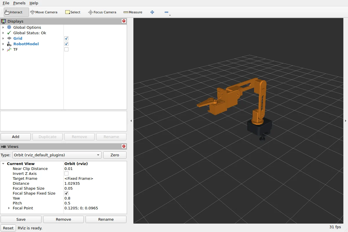
Run it in Gazebo
Gazebo Harmonic and its bridge to ROS 2 come with ros-jazzy-ros-gz. In a new terminal:
sudo apt install ros-jazzy-ros-gz     # once
source /opt/ros/jazzy/setup.bash
source ~/ros2_ws/install/setup.bash
ros2 launch arm6 gazebo.launch.py demo:=true
Gazebo opens with the arm on the ground, fixed where it stands in the design, and RViz beside it shows the robot, its frames and what the wrist camera sees. With demo:=true each joint swings through its range in turn. Every joint is held by a position servo: to move one yourself, publish an angle in radians on its command topic, as the package’s README lists them.
ros2 topic pub --once /wrist_flex/cmd_pos std_msgs/msg/Float64 "{data: 1.0}"Command gripper only. Gazebo Harmonic applies a URDF’s <mimic> only with its bullet-featherstone physics engine, and the package’s world runs DART, the default, which leaves it out. So the package’s mimic_joints.py, which the launch file starts, drives the right finger from the left one’s position.
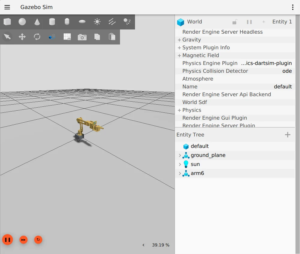
Run it in MuJoCo
MuJoCo needs only Python. Install it with pip install mujoco, then, in the folder where you unpacked the zip:
python -m mujoco.viewer --mjcf=arm6/scene.xmlscene.xml puts the arm, arm6.xml, on a floor with lights. Every driven joint has a position actuator, so the sliders under Control in the viewer’s right-hand panel move the arm, and an equality makes the right finger follow the left. The wrist camera is a MuJoCo camera: choose it under Camera in the Rendering section of the left-hand panel to see through it.
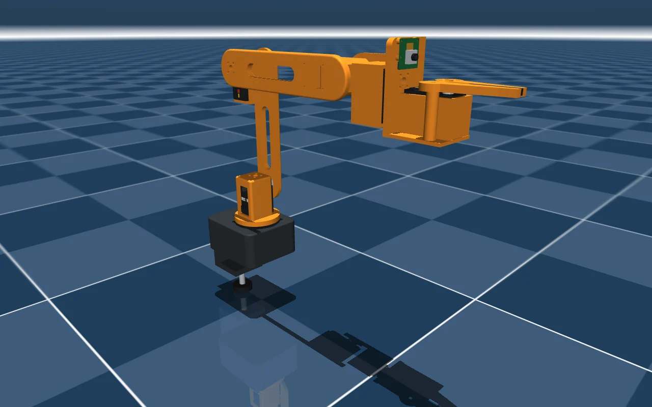
What was checked
The export below was made from the replay on 8 November 2026 and checked with the tools each format is for:
- ROS 2 Jazzy on Ubuntu 24.04:
check_urdfreads the URDF, 10 links in one tree; the package builds withcolcon; with robot_state_publisher running, every link is reachable through tf2; anddisplay.launch.pyopens RViz (above). - Gazebo Harmonic: its URDF reader keeps every link that moves, both free and welded to the world; the world loads and runs for 8 s, the wrist camera’s
imageandcamera_infotopics give messages, andgazebo.launch.pyopens the arm (above). - MuJoCo 3.17: the scene loads with the arm’s 8 links, 7 joints, 6 actuators (the right finger, which follows, has none) and the camera, each actuator’s range its joint’s limits. Driven through a slow sine for 4 s, nothing goes NaN, and the right finger mirrors the left.
- The limits, in the editor: with every other joint at zero and nothing selected, the Interference check finds nothing with the wrist at 90° and 93° down or at 95° and 98° up, and finds the forearm and the wrist meeting at 94° down and at 99° up. The elbow folds 65° and 68° down clear, and at 69° the wrist meets the base and the shoulder. An angle past a limit was typed after the limit had been moved to it in the joint’s panel, since the editor holds a typed angle to the limits.
- Which way each joint turns, each turned alone in MuJoCo: as the table at the top says.
Download the files
- arm6.protojoint.json, 710 KB: the design, to open in the editor with Open, change and export again.
- arm6.zip, 410 KB: the export as it came out, the ROS 2 package with its URDF, SDF, MJCF and 66 meshes, as checked above, with the licence added as
arm6/LICENSE.
Both files are under the MIT licence, copyright ProtoJoint AI: use them, change them and share them, commercially too, as long as the copyright line and the licence go with them.
Questions
Is this the SO-101?
No. It is a desktop arm of the same kind, five joints and a gripper on the same servo, with links of its own. Its URDF comes from its own model, so a change to a link is one export away.
Can I change it and export again?
Yes. Open the design file in the editor (Open), change a part, a finger say, and export again: every link, joint, mass and mesh is written anew.
Why does the gripper have two joints?
Each finger is a link of its own. The left one is driven; the right one follows it through the motion link, which the URDF writes as a <mimic> and the MJCF as an equality between the two joints.
Sources
- Hugging Face, LeRobot documentation, SO-101, accessed November 7, 2026.
- Feetech, 12V 30KG.CM magnetic encoding servo STS3215 (ST-3215-C018), accessed November 7, 2026.
CAD to URDF
Turn a CAD assembly into a URDF in your browser: links from parts, joints from the assembly, inertia from the exact solids. What goes in, what comes out, and a six-servo arm run in RViz, Gazebo and MuJoCo.
CAD to URDF: eight mistakes and how to catch them
Why a robot from CAD loses links, refuses to load or moves wrong in Gazebo and MuJoCo: inertia, default masses, massless links, frames, closed loops, slider limits and heavy meshes, with the check for each.