CAD to URDF
To turn a CAD model into a URDF, build the robot as an assembly, with one part for each rigid link, a joint wherever it moves, a material on every part and the base pinned, then export it. ProtoJoint writes a link for each part, its mass, centre of mass and inertia computed from the exact solids; a joint for each assembly joint, with its origin, axis and limits; and a mesh for each link, in the link’s own frame. The same export writes MJCF for MuJoCo, SDF for Gazebo and a ROS 2 package that builds with colcon and launches in RViz and Gazebo, and the six-servo arm below goes through every step.
What goes in?
The assembly you would build anyway. The export reads the parts, where they stand, the joints between them and the material of each part, so nothing is described twice.
| In the model | In the URDF |
|---|---|
| A part (component) and the bodies in it | A <link>: everything in a part moves together |
| A part inside another, moved by no joint of its own | Part of its parent’s link |
| The part you pinned | The root link |
| A revolute joint with limits | revolute, its lower and upper in radians |
| A revolute joint without limits | continuous |
| A slider joint | prismatic, its limits in metres (it needs them) |
| A rigid joint | fixed |
| A motion link (gears, a rack, two fingers) | <mimic> on the joint that follows |
| A part’s physical material | The density its mass and inertia are computed with |
The model can be made in ProtoJoint, or brought in. A STEP or .sldasm assembly keeps its tree, a component for every subassembly and part (see bringing in an assembly), and a robot that exists only as STL, OBJ or 3MF files can be inserted as parts, each closed mesh with its own mass and inertia (a mesh as a part). Ball, cylindrical, pin-slot and planar joints have no URDF type: the URDF fixes them where they stand, with a warning that says what to use instead, and MJCF keeps them. Robot export has the table for every format.
What does the URDF say?
Here is the left finger of the arm further down, the joint that moves it, and the joint of the right finger that follows it, as the export wrote them:
<link name="jaw_left">
  <inertial>
    <origin xyz="0.022090218307 -0.00308334304336 -0.00297695686914" rpy="0 0 0"/>
    <mass value="0.00661889223981"/>
    <inertia ixx="1.88239721628e-7" ixy="3.29532884254e-7"
             ixz="-3.41793990375e-9" iyy="0.00000282625049978"
             iyz="1.07018051903e-9" izz="0.00000297519061704"/>
  </inertial>
  <visual>
    <origin xyz="0 0 0" rpy="0 0 0"/>
    <geometry>
      <mesh filename="meshes/jaw_left_1.stl"/>
    </geometry>
    <material name="color_f08a24"/>
  </visual>
  <collision>
    <origin xyz="0 0 0" rpy="0 0 0"/>
    <geometry>
      <mesh filename="meshes/jaw_left_1.stl"/>
    </geometry>
  </collision>
  …
</link>
<joint name="gripper" type="revolute">
  <parent link="hand"/>
  <child link="jaw_left"/>
  <origin xyz="0.011 0.00300000000001 0.036" rpy="-1.57079632679 -1.57079632679 0"/>
  <axis xyz="0 0 1"/>
  <limit lower="0" upper="0.785398163397" effort="2.9" velocity="4.7"/>
</joint>
<joint name="gripper_mimic" type="revolute">
  <parent link="hand"/>
  <child link="jaw_right"/>
  …
  <mimic joint="gripper" multiplier="-1" offset="0"/>
</joint>
From the arm’s arm6.urdf, the inertia’s six values wrapped onto three lines. Where it says …, lines are left out: a second visual and collision for the finger’s black pad, and the right finger’s origin, axis and limits.
<inertial>: the link’s mass in kilograms, its centre of mass as theorigin, and the six components of its inertia tensor about that centre along the link frame’s axes, in kg·m². The products of inertia have URDF’s sign:ixyis −∫xy dm.<visual>and<collision>: a binary STL of the link (one per colour, when its bodies differ in colour), already in the link’s frame and in metres, so both origins are zero. The collision geometry is the same mesh.<joint>: itsoriginis where the child link’s frame sits in the parent’s at the joint’s zero, asxyzandrpy; itsaxisis a unit vector in the child’s frame; itslimitholds the joint’s limits and the effort and velocity you set in the export panel. A motion link adds<mimic>, and a spring and damper<dynamics damping>.- Units: metres, radians, kilograms and kg·m², whatever units the design is in.
What else comes in the zip?
One zip named after the package, which unpacks into a ROS 2 workspace’s src/ folder as it is. With every format ticked, the arm’s is 409 KB:
arm6/
  arm6.urdf                    the URDF, its meshes beside it
  urdf/arm6.urdf               for ROS 2: package:// meshes, Gazebo's plugins
  package.xml  CMakeLists.txt
  launch/display.launch.py     RViz, with a slider for each joint
  launch/gazebo.launch.py      Gazebo Harmonic, bridged to ROS 2, and RViz
  config/gz_bridge.yaml  worlds/default.sdf  rviz/display.rviz  rviz/gazebo.rviz
  scripts/demo_motion.py       with demo:=true, each joint through its range
  scripts/mimic_joints.py      moves gripper_mimic with gripper in Gazebo
  arm6.xml  scene.xml          MJCF, and the scene with a floor and lights
  model.sdf  model.config  world.sdf
  meshes/                      66 binary STL files, one per link and colour
README.md<name>.urdffinds its meshes beside it, for tools outside ROS.urdf/<name>.urdffinds them aspackage://<package>/meshes/…, and adds what Gazebo needs to move the robot.- The ROS 2 package is an ament_cmake package.
display.launch.pystarts robot_state_publisher, joint_state_publisher_gui and RViz;gazebo.launch.pystarts Gazebo Harmonic, spawns the robot from its URDF, bridges its topics to ROS 2 and opens RViz. - For MuJoCo,
<name>.xmlis the robot andscene.xmladds a floor and lights. For Gazebo without ROS,world.sdfholds the robot frommodel.sdfon a ground plane. - The README has the commands for each.
package.xml comes with placeholder maintainer and licence lines: fill them in before you share the package.
Where do the mass and inertia come from?
From the solids. Each body’s volume, centre of mass and inertia tensor are computed from its exact shape: for a modelled or imported solid that is its surfaces, not the triangles drawn on screen or a box around it, and a part made of a mesh uses the mesh’s own triangles. They are weighted by the part’s density, turned into the link’s frame and added up about the link’s centre of mass.
A part with no material is weighed at 1000 kg/m³, and the check before the export says so. A part given a mass of its own, such as a servo from the parts library that weighs what its maker says, keeps its shape’s inertia scaled to that mass. Before the files are written, every link with a solid must have a positive mass and an inertia a real object could have: positive about every axis, and no principal moment larger than the other two added together.
How are the frames placed?
- A child link’s frame is its joint’s frame, on the joint axis. Its meshes and inertia are written in that frame, so the link turns about the right point.
- The root link’s frame is at its part’s origin, facing the way the design does, Z up, so the robot stands in RViz as it stands in the editor, however the part itself was turned.
- Each joint’s origin is taken at the joint’s zero, which is the design’s: the joint values in ROS mean what they mean in the editor, and the limits carry over as they are.
- Where the joints happen to be when you export changes nothing.
What happens to gears, grippers and closed loops?
A URDF is a tree. A motion link between two joints, such as a pair of gears, a rack and pinion or two fingers that open together, becomes a <mimic> on the joint that follows, and the ROS 2 package’s Gazebo launch drives the follower from its leader. A closed linkage, such as a four-bar, cannot be a tree: the URDF leaves out the joint that closes the loop, with a warning that names it. MJCF keeps the loop, as an equality constraint at that joint, one joint of the loop driving it.
What happens to the meshes and collisions?
- Each link’s mesh is made from its solids at the Mesh refinement chosen in the panel. Low, the default, loads fastest.
- The collision geometry is the visual mesh. In MJCF the links collide with the floor but not with one another, since MuJoCo collides a mesh as its convex hull, and the hulls of parts that nest overlap where the parts do not.
- A mesh of more than 200,000 triangles is cut into several files, because MuJoCo reads no larger STL.
What does a complete export look like?
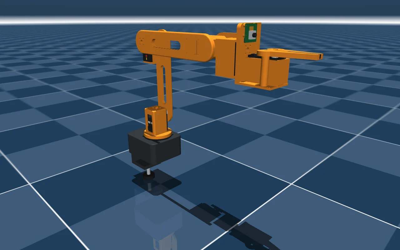
The six-servo desktop arm, exported with every format ticked: eight links with mass and the camera’s two frames, six driven joints and a seventh, the second finger’s, that mimics the first. Each servo rides in the link whose cradle holds it, so a link’s mass is its printed part and the servo inside it:
| Link | What is in it | Mass |
|---|---|---|
base_link | the base block, its desk clamp and the base servo | 427 g |
shoulder | the shoulder plate and the shoulder servo | 89 g |
upper_arm | the upper arm and the elbow servo | 115 g |
forearm | the forearm and the wrist servo | 117 g |
wrist | the wrist and the roll servo | 108 g |
hand | the gripper’s plates and post, the gripper servo and the camera | 113 g |
jaw_left, jaw_right | the two fingers | 7 g each |
Every inertia is one a real body could have. The export panel’s checks come to one warning, that SDF 1.9 has no mimic, and one note, that the servos and the camera carry their makers’ masses. The package passed check_urdf, colcon, tf2 and Gazebo’s URDF reader in ROS 2 Jazzy, ran 8 seconds in Gazebo Harmonic with the camera’s topics giving messages, opened in RViz, and ran 4 seconds in MuJoCo 3.17 with every actuator moving. The arm’s post has the commands, the pictures and the files.
Questions
Do I need to install a CAD program?
No. ProtoJoint runs in a browser tab, and modelling and the robot export need no account. Open the editor, or watch the arm above being built.
Can I start from a model I already have?
Yes. Bring in the assembly as STEP, or as a .sldasm with its part files: it keeps its tree, a component for every subassembly and part. Add the joints, give the parts their materials, pin the base and export. A robot that exists only as STL files can be inserted as parts.
How do I update the URDF after I change the model?
Export again and rebuild the package with colcon build. Every link, joint and mesh is written again from the model, so nothing needs to be kept in step by hand. Edits made to the URDF itself are lost at the next export: make them in the model instead.
Why does my robot fall over or shake in Gazebo?
Most often its masses and inertias are wrong, or a link that has no inertia was left out. The usual mistakes between CAD and URDF goes through them, and through what the check before the export catches.
Which ROS 2 version is the package for?
ROS 2 Jazzy on Ubuntu 24.04, with Gazebo Harmonic for the simulation. That is where the arm above was built and run.
Robot export: URDF, MJCF, SDF and ROS 2
Turn an assembly into a robot description: links from components, joints from assembly joints, inertia from the exact solids, checked before export, as URDF, MJCF, SDF or a ROS 2 package.
URDF, MJCF and SDF export from CAD
Export a robot description from a CAD model in your browser: links from parts, joints from assembly joints, inertia from the exact solids, checked before export, with a ROS 2 package.
Assemblies and joints
Build assemblies from components, connect them with rigid, revolute, slider, cylindrical, pin-slot, planar and ball joints, drive and limit the joints, and check interference and mass.
Importing STEP, .sldprt, .sldasm, DXF, SVG and meshes
Bring STEP, .sldprt and .sldasm, and Parasolid files in as solids; DXF and SVG drawings into sketches; STL, OBJ and 3MF meshes as reference bodies or parts; and pictures to trace.