Templates · Robotics
STS3215 servo bracket
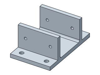
A cradle for an STS3215 (SO-101) servo or any servo of that shape: servo size and clearance, wall height and thickness, side and base mounting holes.
- servo
- STS3215
- SO-101
- SO-100
- LeRobot
- bracket
- robot arm
- 3d printing
- Dwg
- sts3215-servo-bracket
- Params
- 12
- Units
- mm
Parameters
Open in the editor opens the design with these defaults; change them afterwards in Modify › Parameters, and everything that depends on them follows. Opened from the editor’s template library instead (New ▾ › New from template…), the template asks for its values first and checks them against these ranges and against each other, and Copy link gives an address that opens it with your values.
| Name | What it sets | Default | Range |
|---|---|---|---|
servoWidth | Servo body width | 24.7 mm | 12 to 45 mm, steps of 0.1 |
clearance | Clearance each side | 0.2 mm | 0 to 1 mm, steps of 0.05 |
length | Bracket length | 32 mm | 15 to 70 mm, steps of 0.5 |
wallHeight | Wall height | 18 mm | 6 to 40 mm, steps of 0.5 |
wall | Wall thickness | 3 mm | 1.6 to 8 mm, steps of 0.2 |
base | Base thickness | 3 mm | 1.6 to 8 mm, steps of 0.2 |
flange | Flange width | 10 mm | 6 to 25 mm, steps of 0.5 |
sideHoleSpacing | Side hole spacing | 20 mm | 4 to 60 mm, steps of 0.5 |
sideHoleHeight | Side hole height above the base | 9 mm | 2 to 36 mm, steps of 0.5 |
sideHoleDiameter | Side hole diameter | 2.2 mm | 1.6 to 4.5 mm, steps of 0.1 |
baseHoleSpacing | Base hole spacing (along the length) | 20 mm | 6 to 60 mm, steps of 0.5 |
baseHoleDiameter | Base hole diameter | 3.4 mm | 2 to 6.6 mm, steps of 0.1 |
Notes
The servo slides in between the walls along the bracket; the ends stay open for the horn and the cable. Defaults are for the Feetech STS3215 used in the SO-100 and SO-101 arms (body 24.7 mm wide); clearance is added on each side - 0.2 mm gives a snug sliding fit on most printers.
Side holes go through both walls on one line, for screws into the servo body's side holes (or for a clamp bolt across the top of the servo). Measure your servo's holes and set their spacing and height before printing - the defaults are a starting point, not taken from Feetech's drawing. Base holes are in the flanges, for M3 screws into a plate or onto 2020 extrusion with T-nuts.
This is not an official SO-101 part. Print it base down; the rounded wall roots let the walls take a side load without cracking along the first layers.
License: CC0 1.0: no rights reserved.