Templates · Laser and CNC
Keyboard switch plate
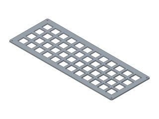
An ortholinear switch plate for MX-style switches: any number of rows and columns at 19.05 mm pitch, with mounting holes.
- keyboard
- switch plate
- ortholinear
- mechanical keyboard
- laser
- cnc
- Dwg
- keyboard-plate
- Params
- 8
- Units
- mm
Parameters
Open in the editor opens the design with these defaults; change them afterwards in Modify › Parameters, and everything that depends on them follows. Opened from the editor’s template library instead (New ▾ › New from template…), the template asks for its values first and checks them against these ranges and against each other, and Copy link gives an address that opens it with your values.
| Name | What it sets | Default | Range |
|---|---|---|---|
cols | Columns | 12 | 1 to 20, steps of 1 |
rows | Rows | 4 | 1 to 8, steps of 1 |
pitch | Key pitch | 19.05 mm | 18 to 20 mm, steps of 0.05 |
cutout | Switch cut-out | 14 mm | 13.8 to 14.2 mm, steps of 0.05 |
margin | Border | 8 mm | 5 to 20 mm, steps of 0.5 |
hole | Mounting hole diameter | 2.2 mm | 1.6 to 4 mm, steps of 0.1 |
radius | Corner radius | 3 mm | 0.5 to 8 mm, steps of 0.5 |
thickness | Plate thickness | 1.5 mm | 1 to 5 mm, steps of 0.1 |
Notes
A plate for an ortholinear (grid) keyboard: square 14 × 14 mm cut-outs for Cherry MX-style switches on a 19.05 mm (0.75 in) pitch, a border round the grid, rounded corners and a mounting hole in each corner of the border.
Columns and Rows set the grid; the plate grows with them (its width is columns × pitch + 2 × border). MX switches clip into a 1.5 mm plate - thicker plates (3 mm acrylic, 5 mm wood) hold switches by friction only, so use plate-mount stabilisers or hot glue. A cut-out of 14.0 mm fits most switches; go to 13.9 or 14.1 if yours are loose or tight.
Laser-cut it from acrylic or wood, or have it cut from aluminium, steel or FR4 by a CNC or laser service: export the outline with Save As DXF from the sketch's right-click menu. The mounting holes default to 2.2 mm, a clearance hole for M2 screws.
License: CC0 1.0: no rights reserved.